

a2dconverterguy
-
Posts
101 -
Joined
-
Last visited
-
Days Won
2
Posts posted by a2dconverterguy
-
-
from chatting to a friend of mine who was using a G-system to change channels on a Mark IV he reckons its something to do with the EXT Amp Control in the Helix sharing a ground ,where the mesa switching requires isolated grounds for each of the switching jacks
Hey Philip
Most Current Production MESA Amps share ground between all of the switching jacks... the problem is that the Helix uses open collector transistors (as opposed to mechanical relays) to switch to ground which most amps don't like...
I guess that the G-system uses the same transistor set-up
I hope this helps
seeya
Joe
-
Hello Gents,
Here is a pictorial on how the CV MOD for Amp Switching works... (As originally envisioned by Doughadfield)
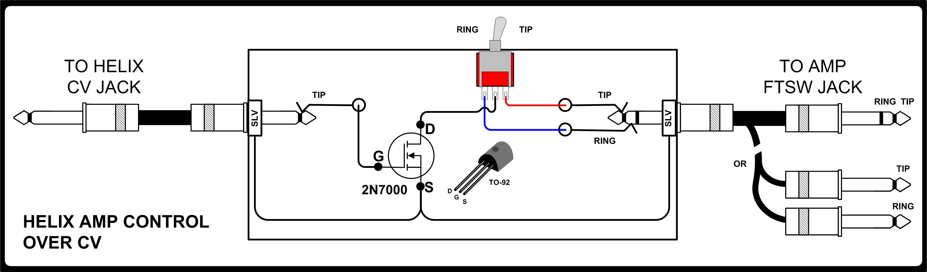
I added a switch to allow you to control one of two functions from the Helix CV... (the TIP or RING on the Amplifier side...)
You can mount the FET/ switch in a small plastic box with two 1/4" jacks.
I hope this helps
seeya
Joe
-
 1
1
-
-
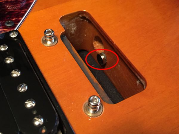
Check whethjer a broken string end fell through to the electronics boards.
I attached a small magnet near the piezo wire access hole to catch loose string ends
I hope this helps
Seeya
Joe
-
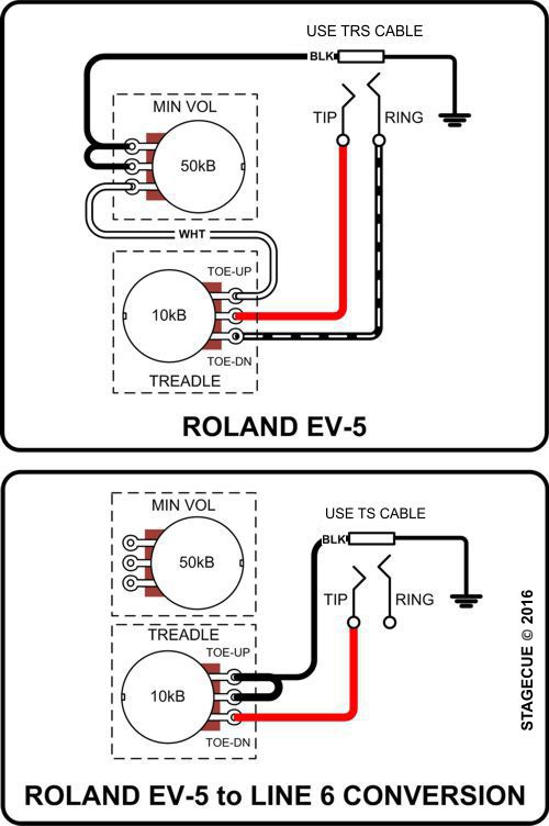
Unfortunately, You'll have to rewire the EV-5 to work...
-
OK, the Editor is cool, but as DI mentioned, the editing on the unit is faster and more fun.... (as long as you have the Helix on your desk or on a stand while editing)...
Looking forward to new Updates!
seeya
Joe
-
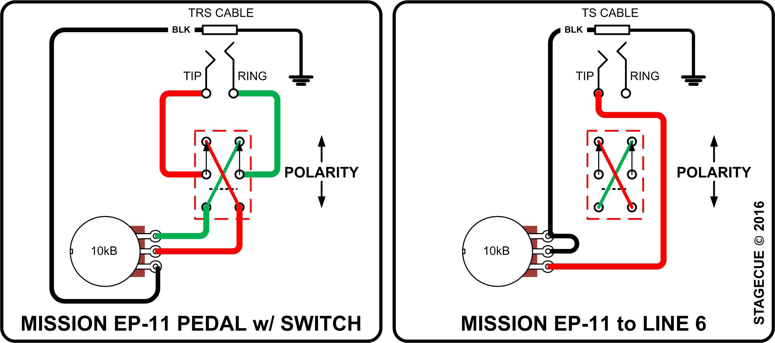
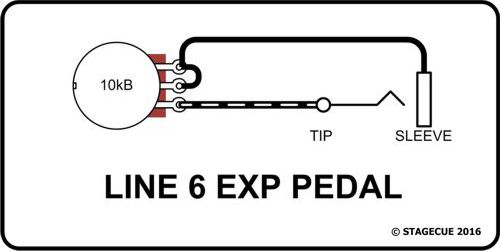
Hello Robberns
This is for the Mission EP-11.
Just rewire as shown and use a TS cable...
I hope this helps
seeya
Joe
-
Can i please address the answer to the topic by the Line 6 Staff member,
can you please tell me then what is different about the Line 6 EX-1 to the Roland EV-5???
Is the wiring different or is it to do with a Mono or TRS cable??
Thanks
Both the wiring and use of a TS cable are different as follows...
I hope this helps
Seeya
Joe
-
Hey Spikey,
Just a standard TS cable will work and the Helix will auto-calibrate the pedal automatically.
Good-Luck
seeya
Joe
-
Hey Spikey...
Solder the wires like this...

don't worry about the pot value
I hope this helps
seeya
Joe
-
The 6-string acoustic models sound like an electric instrument. I'm wondering if it's the settings you are using on the Helix? An acoustic model really wants to be run "straight-through" with possibly a bit of equalization and compression.
Also, hard to make a call on the Lester bits with that amount of overdrive.
I'm particularly interested in what Spank position 2 sounds like through, e.g. a clean Fender Twin emulation.
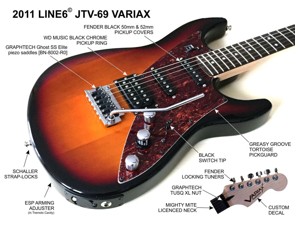
FYI: I have that same Mighty-Mite neck on my JTV-69 and really like the way it plays.
The acoustic sounds are JTV 1/4" output to Helix AUX IN with slight compression and slight Plate reverb.... I forgot to turn off the Global EQ !!!!.. I re-recorded the acoustic parts... I mainly wanted to show the lack-of-plink sound that I had previously with the stock Low E piezo
https://soundcloud.com/dirty-hurricane/line-6-jtv-69-with-graphtech-piezos
seeya
Joe
-
Can you post a recording of the guitar using the Graphtecs?
Here's a quick recording I did on the JTV with Graphtech saddles...all of the Acoustic Models through the Helix AUX IN and the Lester model through different Helix amps.... comments welcomed.
I recorded with some Helix hi-gain patches to show the lack-of-plink sound that I had previously with the stock Low E piezo
EDIT: the below is a new link with the Helix Global EQ turned off on the Acoustic models :D
https://soundcloud.com/dirty-hurricane/line-6-jtv-69-with-graphtech-piezos
seeya
Joe
-
I'm curious about the neck itself...which Mighty Mite model did you choose?
Mighty Mite Fender Licenced Neck from StewMac (# 5713 Compound Radius)
I hope this helps
Seeya
Joe
-
Do the setscrews line up properly with the little grooves on the bridge plate? I think I remember someone on this forum mentioning a problem with getting the bridge pieces to lie flat because of a small difference in screw spacing.
Hey S.H.
The L.R. Baggs Piezos have a pointy set-screw and the Graphtech Piezos have a flat set-screw
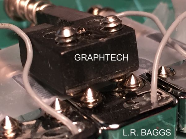
The spacing difference is minimal (0.240" for the L.R. Baggs versus 0.237" for the Graphtech)
Once the guitar is strung-up everything works fine!
seeya
Joe
-
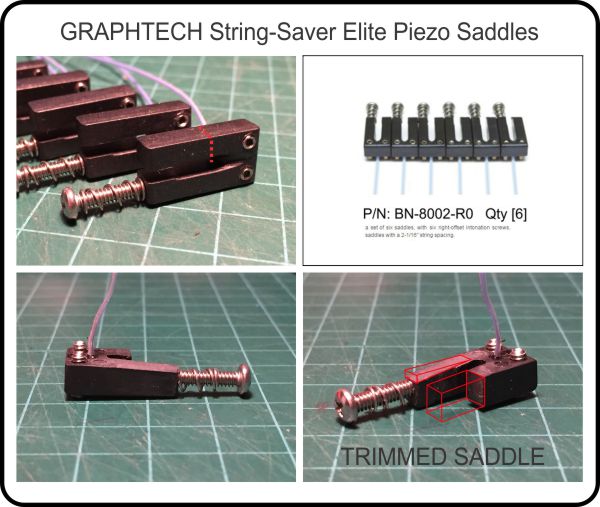
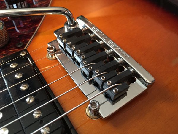
Nice Job! Your trimming to prevent the saddle touching in the rear is critical! Saddles also can't touch each other or there will be way more crosstalk. Crosstalk kills alternate tunings.
Hi Charlie, Thanks for the kind comments...
I have around 0.007" clearance between saddles... I had to file the sides of a few saddles to get this clearance.
seeya
Joe
-
Hey Guys
I went back to my experiment to replace the Stock Saddles on my JTV-69 with Graphtech saddles...
Previously, the extraneous noise that I was experiencing was due to a saddle wire that had broken making the Graphtech system unusable....
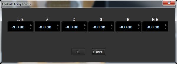
When I went to give a second gallant effort, the wire on the 6th saddle just came off... after ordering a replacement saddle, re-installing the bridge on the guitar, and setting the global string levels in Workbench, I was very happy with the results!!
Here are the Workbench Volume settings...
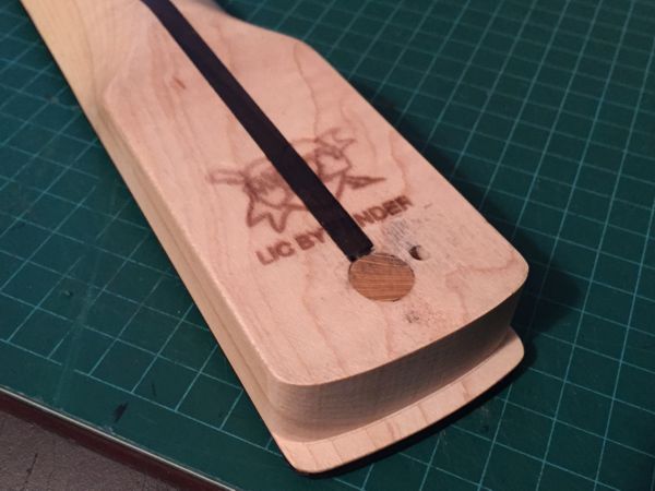
I also had to trim the saddles to allow easy string changes and so that the saddle was not making contact with the bridge plate directly...
Here are some more pix...
I also glued a small permanent magnet near the piezo wire access hole to catch broken string ends from getting to the electronics cavity
Another thing that I found after extensive testing was that the "plink" has disappeared on the 6th string...
Previously I was able to create the "plink" very easily with palm muting... now, nothing!. That made me very happy.
Good luck to those who are trying to make the Variax as powerful as it can be!!
Seeya
Joe
-
Hi Rudi,
I'm not sure which internal mod Line 6 provided to JC, but, I suspect with high confidence that they installed 2 relays anchored and wired internally.
This is a high-risk mod unless you have electronics experience and it would void your warranty.
(After removing the cover and all of the nuts and screws holding the I/O board to the chassis, the mod would include un-soldering & removing the dual CV/ EXT 1/4" jack from the PCB. Then you would need to cut the pins on the EXT jack part 'short' so that they do not make contact with the circuit board anymore. Then you would wire the relay board to the jack pins and PCB traces and find a place to tap 5VDC and ground for the relay power)
The Relay board would look something like this 5V 2-Channel Relay Module Expansion Board....
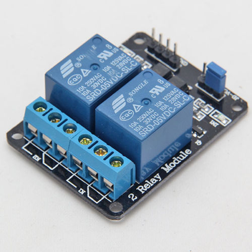
Again, I wouldn't do anything internally on the Helix until your warranty is up.
I hope this helps
seeya
Joe
-
Hi Josh
I'm glad that you were able to get the switching on your MESA working with the HELIX ext. switching....
Unfortunately, as you found, the only way to get the switching to work is by using relays... I will try to answer your questions...
The LEDs in my schematic are not necessary....
You need two separate relays to switch the two functions... the above relay (G6E-134P-ST-US) is available with a 5 VDC coil, but, I'm not sure how much current the CV jack on the Helix can Sink... Good idea though....
Someone at Line6 might comment on using the CV jack as a low current power supply to drive some small relays...(the current draw for one 5VDC relay is 40mA.)
Seeya
Joe
-
Here's the typical circuit.... Larger pot values will work as well....
I hope this helps
Seeya
Joe
-
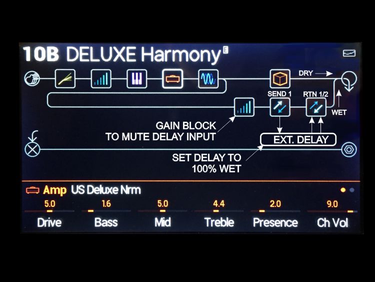
Why not just use the FX Loop block rather than separate send and return blocks? Is your reasoning that you just need a mono send and a stereo return? I can see the logic in that, but everything in front of the loop is mono anyway with the tone you showed, so you wouldn't be losing any stereo information. You might find you want to bump the send level up to compensate. That way you can still keep the trails turned on.
Hi Phil,
Not having so much experience with the FX Loops I didn't realize that there was an FX loop option (I didn't scroll down past the Sends and the Returns in the FX selection :) )
One less block than what I first designed... thank-you
seeya
Joe
-
1
-
-
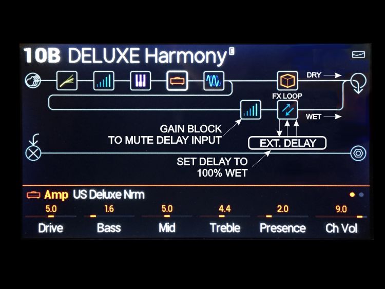
So here's the problem. I am sending signal to my delay via send 3 and getting a stereo return from 3/4. A stereo return does not have the ability to enable trails. Seems like it would be an easy software patch to fix it. Hopefully it's in the next batch.
Here's a solution...
Put Your Send/ Return block in a parallel path and mute the input of the send with a Volume Block...then the delays will trail as the Delay outputs will still be connected to the mixer
Here's an example...
Remember to Turn Your delay 100% WET so you don't mess up your dry signal with a phase shift.
I hope this helps
seeya
Joe
-
2
-
-
Hey DJ...
Here's a pic of the relay...
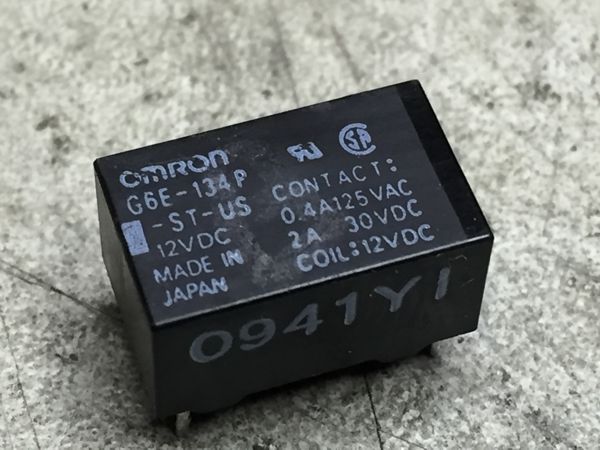
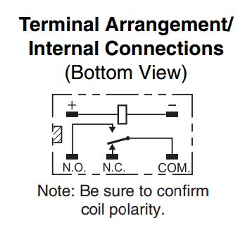
standard OMRON, G6E-134P-ST-US (12VDC)
There is a 9 V coil version, but, the 12 VDC coil works fine at 9 VDC... I hope this helps.
seeya
Joe
-
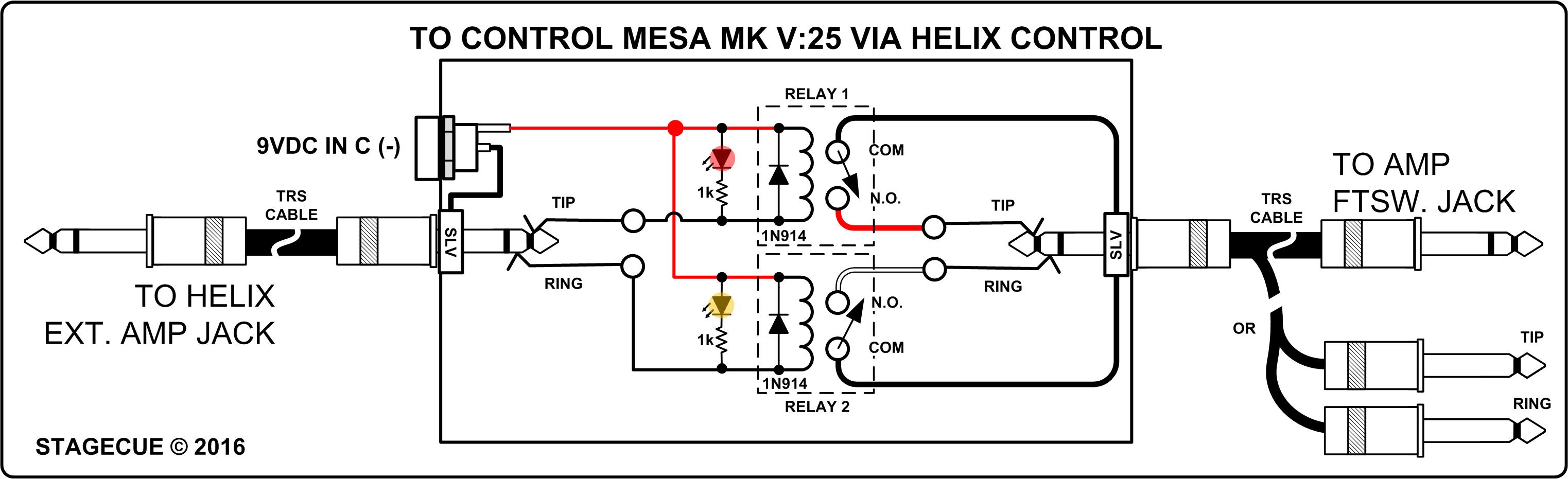
Howdy Folks,
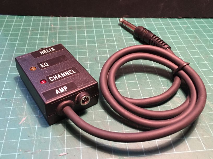
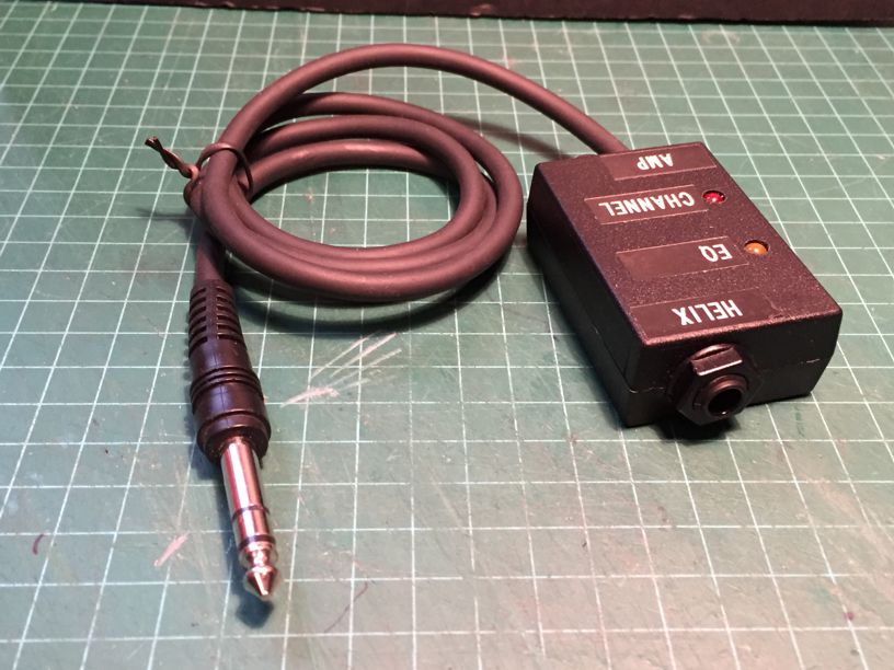
I was successful in getting the Helix to control the Mesa Boogie MKV:25...
The box has two relays that isolate the two switching functions... it is shown powered by a 9V Battery, but ,an FX power Supply works as well.
Instead of the short pigtail and single 1/4" phone jack, the box would probably be more useful with two 1/4" phone jacks... then you could use a long and short TRS cable to place the interface near the Amp or near the Helix... (wherever it's easiest to get power for an adapter.)
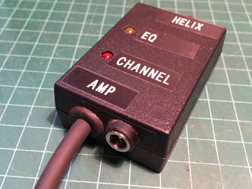
Here are some pix of the interface box...
Based on this schematic if you want to build one yourself...

Here's a video showing the operation...
seeya
Joe
-
3
-
-
It looks like Line 6 is using open collector transistors for switching to ground as opposed to using relays.
There seems to be an isolation problem between the EXT control 1 and EXT control 2 that might be mitigated by increasing the stated 11k resistance. The most reliable way is by using relays, like in the below pic, which I will wire up and test.
The only drawback is that the relays need power, so you will need to provide 9VDC to the interface box.
Seeya
Joe
-
 2
2
-
3
-
-
Sorry Guys,
I do not have a Mini Rec or MKV:25... I originally pulled this resistor info from the Helix FAQ which has been superseded by this statement...
http://line6.com/support/page/kb/_/effects-controllers/helix/helix-and-ext-amp-controlling-r791
"Helix’s ability to control external amp channel and/or reverb switching has been tested with many popular amps and heads. Unfortunately this does not guarantee compatibility with all products. Note that, depending on the circuitry of the channel switching jack in the guitar amp used, the EXT Amp function may not operate as expected."
After doing some research, I found that Elantric from V-Guitar Forum proposed that LED's present in the MESA footswitch might be part of the solution to the puzzle...
I am trying to figure out if this could work....I'll report back
seeya
Joe
-
1
-
Allow "CV" output to double as a 2nd "Ext Amp" controller.
in Helix
Posted
Here is the drawing that I posted to another thread regarding Amp Switching using the Helix CV Jack.. I thought that it would be appropriate for this to follow the original thread...
Below is a Schematic outlining how the CV MOD for Amp Switching works... (As originally envisioned by Doughadfield)

I moved the FET from Doug's cable plug to a small box with 1/4" in/ out jacks and a switch to allow you to control one of two functions from the Helix CV... (the TIP or RING on the Amplifier side...)
I hope this helps
seeya
Joe