
edstar1960
-
Posts
976 -
Joined
-
Last visited
-
Days Won
6
Everything posted by edstar1960
-
 MiroslavKloud reported that his JTV59 was with Line6 tech support for months and if I remember correctly, they did replace many parts, however, not sure if they actually replaced the piezo's or complete bridge or not. Would be interesting to hear from MiroslavKloud whether his guitar did get new piezo's or not as that would provide evidence one way or another. If the fix is as simple as just replacing the piezo's wouldn't Line6 have done that for him? Especially as they had it for months and apparently tried many other things? And all the other reports of guitars that went in under warranty to have this problem fixed and all came back modified and supposedly "fixed" BUT still have the problem - surely Line6 would have just been replacing the piezo's if that fixed the issue? Wouldn't they? Or perhaps the piezo's have been getting replaced and the problem persists because either the replacement piezo's are also faulty OR the fault lies in a combination of other factors that will manifest the problem even with perfectly functioning piezo's??
 -
Make Your Variax Sound 100% Better
edstar1960 replied to katiekerry's topic in James Tyler Variax Guitars / Workbench HD
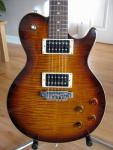
I don't need the velcro dampeners on my JTV59 and I didn't need to file the piezo saddle slots. The heat shrink tubing around the string tails and the electrical tape on the back of the bridge resolves the metallic overtones I was getting with my particular JTV59. I believe the issue in my case is just the resonance of the bridge combined with the sensitivity of the piezo's and the movement of bridge parts following pick action and pick scraping sounds being picked up which leads to the all these unwanted metallic overtones coming through in the modelled signals. No problems when using mags only. I also think that once your ears tune into a particular odd or unwanted artifact from the guitar that you can't "unhear" it even if in reality it is not that prevalent and may not be noticed by anyone else. Also, because it is a modelling guitar I scrutinize each modelled sound much more than I would a standard guitar, so there are probably subtle nuances that may be on a standard guitar but not noticed, but they really stand out in the JTV modelled sounds. If anyone has a JTV that exhibits the peculiarities (plinks, metallic overtones etc) mentioned in this discussion thread, then one of the suggested solutions may well resolve the issue for them. YMMV Remember though, that plenty of people report they don't have any problems with their JTV - so you may well be lucky when ordering a new one - but you won't know until you get one in your hands and try it yourself with your amp etc. And if it's a bad one then you can always return it as long as you buy from a reputable company with a returns policy - so no risk involved. -
Make Your Variax Sound 100% Better
edstar1960 replied to katiekerry's topic in James Tyler Variax Guitars / Workbench HD
Decided to abandon the new tail piece as I could not get rid of the extra unwanted metallic semi-acoustic overtones. So I reverted back to the standard bridge BUT this time I coverd the string slots with electrical tape and pushed it into the slots as best I could, then I used some small diameter heat shrink tubing over the tails of the strings and I restrung my guitar. See picture. NB: I have locking machine heads so that made the restring a lot easier as I had to shove the ball ends into the slots and tug the strings into the grooves to get them to fit and to keep the heat shrink tuning in place. It would probably be even better if you can get smaller diameter heat shrink tubing than I used - but that was the smallest diameter I could find and it did the job for me. I think it will work just as well using only the heat shrink tubing - the electrical insulation tape is probably unnecessary. End result - it's not pretty BUT it has eliminated all the unwanted metallic overtones or plinks I was getting. So big improvement on all modelled tones via the piezos. YMMV. -
Make Your Variax Sound 100% Better
edstar1960 replied to katiekerry's topic in James Tyler Variax Guitars / Workbench HD
NB: Quick update: Noticed that the strings did not align directly across piezo and through gap in saddle block - better alignment of the strings and better placement of the Velcro did reduce the metallic semi-acoustic overtone. More experimentation required.... -
Make Your Variax Sound 100% Better
edstar1960 replied to katiekerry's topic in James Tyler Variax Guitars / Workbench HD
OK - when I tried my JTV59 acoustically with the new tail piece it sounded great - however - when I connected the JTV59 using VDI to my HD500 and played using the model sounds and the piezo's, I immediately became aware of a metallic semi-acoustic type sound mixed with each model I tried - almost as if I was mixing a dobro or resonator body with each one. I then noticed that if I just tapped on the body of my JTV59, that I could hear a loud audible tap through the piezo's and if i tapped the tail piece I could hear a loud thump through the piezos, and if I tapped the string tails I could also hear that sound through the piezos. So although I had placed velcro over the tails, and it had suppressed the ringing, it was not suprrsing any other transmitted vibration. The tail piece I bought was cheap, so it is probably made out of cheap metal alloy covered in chrome, and it appears to be very resonant, and as it is fixed to the body by a large metal plate, there is a lot of contact area so a lot of body vibration is able to come back into the strings. I will try to see if I can dampen the resonance from the tail piece any further to see if it is possible to get it under control or less noticeable, but I don't think I am going to have any luck. Unfortunately, it is looking very much like the tail piece is not going to make things better for me and I will have to revert back to the original set up and look at lining the original bridge grooves with insulation tape or continue wrapping the tails of my strings before fitting them. I will post an update once I have finished experimenting. -
Make Your Variax Sound 100% Better
edstar1960 replied to katiekerry's topic in James Tyler Variax Guitars / Workbench HD
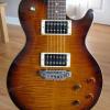
Finally got around to fitting my new tail piece to my JTV 59 as per katiekerry. Here are the pictures. NB: The white strips near the nut and the bridge are pieces of self-adhesive Velcro with the backing paper still in place. These are in position to stop extraneous ringing between the nut and machine heads and between the saddles and the tailpiece. -
HD500X understanding footswitch LED with multi effect assignment
edstar1960 replied to mariosr's topic in POD HD
Was the LED for the footswitch ON when you saved the patch? I can't remember whether the LED status is affected by the order the fx appear within the chain OR whether it is affected by whether it is ON/OFF when you assign the last fx to it. Something in the back of my mind tells me that it is controlled by the order they appear in the patch. Can't double check at the moment. I know that when I have done this, I normally have set the FX to the one I want ON by default when I switch to the patch, (in other words - saved the patch with the fx I want ON actually ON and the other one OFF), then when I press the footswitch it toggles that one off and toggles ON the 2nd fx. I don't usually worry about whether the LED is ON or OFF when the patch is saved, and whether it is ON or OFF when I then re-select the patch. I just know that if I press the selected FS that it will toggle between the 2 fx I have assigned to it. So whether it is ON first and the goes OFF, or whether it is OFF first and then comes ON, it doesn't really bother me as it still toggles one fx off and one on. -
Jasonk931 - yes - I am referring to the 1/4" outputs. If you want to be able to run two exact copies of any patch which may contain any combination of fx's etc, then the simplest solution is to take a lead out either the L or R 1/4 inch output - if you only use one 1/4 inch lead the HD500 sums the L and R channels to mono automatically for you. Take that single output and put it into the Y socket of an ABY splitter box which allows you to have BOTH the A and B outputs on. Then you will get 2 identical line level signals to run with 1/4 inch jack leads to two separate amplifier sources. If you don't mind creating your patches so that they always result in two identical mono signals on the L and R output channels within the HD500, which means considering placement of stereo fx, and possibly having to use a noise gate at the end to sum to mono, and possibly placing your chain before the mixer block in the unit - all depending on how you want to do it - then you can create two identical outputs at the Land R 1/4 inch sockets within the HD500, and that way you don't need to utilise a separate ABY box to split the signal after the HD500. My thinking is this - leave your patches the way you have them set up - so they work as you expect at home or when recording etc and you don't need to worry about stereo fxs and summing to mono etc - and then take the HD500 to church and plug the /4" output into the Y socket of an ABY box and then take the A and B sockets and connect them to your 2 different amplifiers. Done. Just make sure that the ABY box supports both A and B being active at the same time. The Fender ABY box does exactly this. It's entirely up to you which method you use. Hope this has helped you decide. Good luck.
-
If you want to have two summed mono outputs instead of just one then you can take the 1/4" out from either the L or R into an ABY box that is capable of having both A and B on at the same time. That will keep the summed mono output of your HD and split it into two identical signals to feed two diferent amps/mixers etc. The FENDER ABY Box 2 button passive footswitch (RED) will do this perfectly and it's an inexpensive option.
-
Variax Path A, & Mic Path B, assigned to separate outputs POD HD500X
edstar1960 replied to Cobdog's topic in POD HD
I noticed from the picture of your monitor that Input 2 has a mic/line input button option but Input 1 does not, therefore, I suggest you run the XLR to Input 1 as that is mic level so will match, and for input 2 set the button option to LINE and then run the 1/4 inch to that. That will attenuate the hotter signal. So for the set up we have been talking about, I suggest you take the Pod R XLR out, which should have your mic signal, and run that to the Monitor1 Input 1, then take the Pod L 1/4 inch out which should have your Variax signal and run that to Monitor1 Input 2, with the input set to LINE. Then for Monitor2 do the reverse, which is take the Pod L XLR out and run that to Monitor2 Input 1, and take Pod R 1/4 inch out and run that to the Monitor2 Input 2 with input set to LINE. Then use the Volume controls on each channel on each monitor to adjust desired volume levels. That will give you exactly what you want with full control from both monitors. -
Variax Path A, & Mic Path B, assigned to separate outputs POD HD500X
edstar1960 replied to Cobdog's topic in POD HD
Yes, you are correct. As radatats has already confirmed - daisy chaining monitor 2 from monitor 1 will still allow you to control the individual volumes of mic and variax on the monitor 1 which is taking the output signals from the Pod. Just make sure that your link output control switch on monitor 1 is set to take both Input 1 and Input 2 signals and send them out via the link. Give it a try and see how it works out. -
Variax Path A, & Mic Path B, assigned to separate outputs POD HD500X
edstar1960 replied to Cobdog's topic in POD HD
Yes you are. Apologies if it was not clear before. The suggested approach allows you to use 2 cables. One cable for the L output carrying the Variax signal and one cable for the R output carrying the Mic signal. You can choose whether to use the XLR outputs from the Pod or the 1/4 outputs. That depends on whether you want a mic level input or a line level input into your monitors. Your monitors have 2 inputs available - each with volume control - one input will take the L output feed from the Pod (the variax signal) and the other will take the R output feed (the mic signal). That gives you what you want - individual and separate control at the monitor of the Variax and Mic signals. -
Variax Path A, & Mic Path B, assigned to separate outputs POD HD500X
edstar1960 replied to Cobdog's topic in POD HD
No you don't need to feed both XLR and 1/4 outs of the Pod to your monitors - you can choose to use EITHER the XLR outs or the 1/4 outs of the Pod to feed the inputs of your monitors. Be aware that the XLR outs produce mic level signal and that the 1/4 outs produce LINE level or AMP level depending on what you have the 1/4 switch on top of the Pod set to. The LINE level output signal choice gives you the strongest (loudest) signal strength. Also, as Radatats pointed out, be aware that if you only use one 1/4 out that it will automatically sum both L and R channels to that one output. So if you want to keep the L and R channels separated you need to use both L and R 1/4 outputs - don't just use one. And as Hurghanico pointed out that if you use a stereo fx in last position on either path A or B that you will need to follow it with a mono fx to sum both halves of the stereo signal back to mono, otherwise you lose half the stereo signal, which may or may not be significant depending on the stereo fx. eg: the analog chorus stereo fx only outputs the fx on one side - so if you didn't sum it to mono then you would either have just the dry signal or full fx signal rather than a mix of both. -
Variax Path A, & Mic Path B, assigned to separate outputs POD HD500X
edstar1960 replied to Cobdog's topic in POD HD
I think the best option for you is to PAN hard L and hard R the paths A and B on the POD mixer block and ensure you don't put any effects in the pre-path before the split - keep the Variax fx blocks on Path A and the Vocal fx blocks on Path B. That way the Variax output will be only coming out of the Pod L outputs and the Mic outputs will only be coming out of the Pod R outputs. You can then send the L and R to the appropriate inputs on your monitors and control the volume with the dedicated monitor volume knobs for each input. -
In addition to the differences Silverhead pointed out, the other differences in signal flow that need to be noted are where the digital/analog conversions take place: VDI - the magnetic pick-up signal is converted to digital on the JTV before being sent down the VDI to be processed by HD500 or Helix and the modelling (piezo) signal stays digital down the VDI to be processed by HD500 or Helix (no conversion) and both signals finally get converted back to analog before being output from the HD500 or Helix 1/4 or XLR outputs. 1/4 - the magnetic pick-up travels down the cable as analog and gets converted to digital within the HD500 or Helix and the modelling (piezo) signal gets converted from digital to analog in the JTV sent down the cable and then converted back to digital in the HD500 or Helix and both signals finally get converted back to analog before being output from the HD500 or Helix or XLR outputs. So, the different connections process and transmit the signals differently and have a subtle effect on the sound produced. Some people are far more sensitive to those differences than others. If you want to use the VDI but prefer the sound that the 1/4 connection makes then the only solution at the moment is to use the available EQ options within the HD500 and Helix and/or guitar model adjustments via Workbench to adjust the VDI signal to sound more like the 1/4 inch.
-
Thanks again psarkissian for offering to help out - much appreciated. I am on FB ad Linked in too so should be easy to contact people to ask a question or two if the need arises.
-
Thanks psarkissian. I am not planning on doing the swap just yet - certainly not in the near future - just wanted to know whether it was possible in case I had to do it if I encountered insurmountable issues with my stock bridge. I met Tim Morgan at the Rugby office couple of years back - he helped me when I had problems with my first JTV59 (one from one of the first batches) and arranged for it to be replaced with the one I currently have. Great guy! Not sure how I would get hold of him now though as I only had his work contact details. Worth knowing though.
-
All functions on this forum used to work fine for me under IE - however - moved to latest IE and suddenly the QUOTE button no longer works for me. No idea why - but I haven't wasted any time trying to fix it.
-
Same here. Pedal calibration never returns the quoted values the first time I try. I usually have to repeat it a few times and I make sure I do everything nice and slowly and I don't try to press the pedal too hard - I just move it from Min to Max slowly - sometimes I just use my hand. Some times I just press the C button and try the MIN-MAX move again and maybe do that 3 or so times instead of going through all the steps again. I can then get the 0 - 255 readings. You will get there.
-
No it's not limited - it just means you have to press two switches to navigate to the next patch rather than go direct as in the ABCD mode. You can still have multiple patches all saved ready for use in FS5-8 pedal board mode. And if you only do it in between songs then you have plenty of time to swap to the next patch.
-
If you only change patch (preset) between songs then why not always use FS5-8 pedal board mode? That way you can have the effects you want to toggle on/off during a song on the bottom row of FS as you prefer. Then at the end of the song you simply use the BANK Up/DOWN footswitches followed by the A/B/C/D selection to get to the next pre-programmed patch with a new set of FX for the new song.
-
Remember our prices include 20% VAT. So the new price without tax is about £540. Some places are letting them go cheaper than that over here - I have seen an ex-demo JTV59 offer for £570 including the 20% VAT - so that's about £480 without tax. And of course - the base price is always higher over here anyway ... :)
-
All the JTV models I can see on sale in the UK are all at "new lower price" around £650 and labelled "while stocks last". The Standard is about £470 over here. The JTV is a bargain at that price - so if you want a backup or want one for the first time now is the time to jump in. No idea how much stock is left but once it's all gone I doubt there will be any more new ones - it will just be the "used" market if you want one.
-
Just to clarify - the Global EQ does not apply to the L6 Link outputs either.
-
Thanks for posting the video MiroslavKloud - I can clearly hear that horrible clanging overtone on the low E. I hope Line 6 address this issue and fix it for all affected users. I am incredulous that they had it for 11 weeks and didn't fix it and in fact stated they could not hear anything wrong with it. What is going on????
